Well ASCII file format
OBJECT WELL Name
[CRS Authority Code Name HorizontalUnit]
[CSYSTEM Easting Northing TVDSS Inclination Azimuth]
[UNITS EastingUnit NorthingUnit VerticalUnit InclinationUnit AzimuthUnit]
[COLOR Red Green Blue [Alpha]]
[UNKNOWN UnknownValue]
[COORDINATES WellEasting WellNorthing DFE]
[WELLTYPE WellType]
[WELLSTATUS WellStatus]
WELLBORE WellBoreName
[COLORWB Red Green Blue [Alpha]]
[TIEIN MDTieIn InclinationTieIn AzimuthTieIn EastingTieIn NorthingTieIn TvdssTieIn]
[STATIONS StationSpecificationType]
Easting Northing TVDSS MD Inclination Azimuth |
Easting Northing TVDSS MD |
Easting Northing TVDSS |
MD Inclination Azimuth
....
[
SIDETRACK SideTrackName KickOffDepth [ParentWellBoreName]
[COLORWB Red Green Blue [Alpha]]
[STATIONS StationSpecificationType]
Easting Northing TVDSS MD Inclination Azimuth |
Easting Northing TVDSS MD |
Easting Northing TVDSS |
MD Inclination Azimuth
....
]
Keywords (the order of these keywords does not matter, except from the OBJECT keyword – this keyword should always be the first one – and the STATIONS keyword; this keyword should always be defined after the corresponding WELLBORE or SIDETRACK keyword)
| Keyword | Description | Optional | Comment |
|---|---|---|---|
|
WELL |
Specifies the object type in this file |
No |
One value is expected: 1. Name of the well |
|
WELLSTATUS |
Specifies the well status |
Yes |
One value is expected: 1. Status of well (default = EXISTING) When this keyword is not included, the value is assumed as EXISTING well |
|
WELLTYPE |
Specifies the well type |
Yes |
One value is expected: 1. Type of well (default = UNDEFINED) When this keyword is not included, the default type is applied |
|
COORDINATES |
Specifies the well coordinates (easting, northing + Derrick Floor Elevation) |
Yes |
Three values are expected: 1. Easting 2. Northing 3. DFE DFE is a negative depth but positive elevation. |
|
AZIMUTHREFERENCE |
Indicates that all azimuths exported from JewelSuite Geomechanics are referenced to Grid North. |
Yes (Not present in files exported prior to release JewelSuite Geomechanics). |
Has one possible value: 1. GridNorth |
|
TRAJECTORYDEFINITION |
Used internally to indicate which type of trajectory data was active for this wellbore at the time it was exported. Thus its setting determines which trajectory data type is used on import. |
Yes (Not present in files exported prior to release JewelSuite Geomechanics). |
Allowed values are: 1. DeviationSurvey 2. PositionLog |
|
WELLBORE |
Main wellbore section |
No |
Two values are expected: 1. WellBoreName 2. WellBoreType (optional – default = EXISTING) Only 1 WELLBORE keyword can be specified per WELL. All other wellbore need to be SIDETRACK wellbores |
|
COLORWB |
Color of the wellbore |
Yes |
Four values are expected: 1. Red (0-255) 2. Green (0-255) 3. Blue (0-255) 4. Alpha (0-255 – default = 255) When this keyword is not included for the current object, the color will be used from the parent well object |
|
TIEIN |
Specifies the wellbore tie in values |
Yes |
Six values are expected: 1. MDTieIn (default = 0.0) 2. InclinationTieIn (default = 0.0) 3. AzimuthTieIn (default = 0.0) 4. EastingTieIn (default = 0.0) 5. NorthingTieIn (default = 0.0) 6. TVDSSTieIn (default = 0.0) When this keyword is not included in the file, all values are assumed as 0.0 This keyword is ONLY used in context with the WELLBORE keyword; SIDETRACK wellbores do not need the TIEIN keyword. |
|
SIDETRACK |
Define a sidetrack section |
Yes |
Two values are expected: 1. SideTrackName 2. SideTrackType (optional – default = EXISTING) Multiple SIDETRACK keywords can be specified per WELL. Only the first wellbore need to be defined with the WELLBORE keyword |
|
STATIONS |
Define the way stations are specified |
Yes |
One value is expected: 1. StationSpecificationType (default = AHD_ANGLES) When this keyword is not included, the values is assumed as AHD_ANGLES (e.g. Ahd, Inclination, Azimuth only) |
Variables
| Variable | Description | Description | Min | Max | Comment |
|---|---|---|---|---|---|
|
WellNorthing |
Northing well location |
double |
- |
- |
Default = 0.0 |
|
WellEasting |
Easting well location |
double |
- |
- |
Default = 0.0 |
|
DFE |
Derrick Floor Elevation value |
double |
- |
- |
Default = 0.0 DFE is a negative depth but positive elevation. |
|
WellBoreName |
Name of the wellbore in this well |
string |
- |
- |
No spaces allowed |
|
ParentWellBoreName |
Name of the parent wellbore to attach the sidetrack to |
string |
- |
- |
No spaces allowed when the parent wellbore is not specified, the previous wellbore is the file is assumed to be the parent wellbore |
|
KickOffDepth |
Kick off depth of a sidetrack (ahd value at parent well bore) |
double |
- |
- |
Value should be between start and end ahd of specified parent wellbore |
|
WellStatus |
Status of the well |
int |
1 |
3 |
1 = EXISTING 2 = PLANNED 3 = UNDEFINED |
|
WellType |
Type of the well |
int |
0 |
14 |
0 = UNDEFINED 1 = RBWATINJ 2 = STBWATINJ 3 = RBGASINJ 4 = MCFINJ 5 = STBOIL 6 = MCF 7 = MCFWET 8 = STBLIQ 9 = RBTOT 10 = RBOIL 11 = RBGAS 12 = RBWAT 13 = RBLIQ 14 = STBWAT |
|
MDTieIn |
Measured depth tie in value |
double |
- |
- |
Default = 0.0 |
|
InclinationTieIn |
Inclination tie in value |
double |
0 |
180deg |
Default = 0.0 |
|
AzimuthTieIn |
Azimuth tie in value |
double |
0 |
360deg |
Default = 0.0 |
|
NorthingTieIn |
Northing tie in value |
double |
- |
- |
Default = 0.0 |
|
EastingTieIn |
Easting tie in value |
double |
- |
- |
Default = 0.0 |
|
TVDSSTieIn |
TVDSS tie in value |
double |
- |
- |
Default = 0.0 |
|
StationSpecificationType |
Specifies the way the stations are represented in the file |
int |
0 |
3 |
0 = AHD_ANGLES 1 = XYZ 2 = XYZ_AHD 3 = XYZ_AHD_ ANGLES |
|
MD |
Measured depth value of the station |
double |
- |
- |
|
|
Inclination |
Inclination value at station |
double |
0 |
180deg |
|
|
Azimuth |
Azimuth value at station |
double |
0 |
360 deg |
|
|
Northing |
Northing station location |
double |
- |
- |
|
|
Easting |
Easting station location |
double |
- |
- |
|
|
TVDSS |
TVDSS station location |
double |
- |
- |
Example 1 (vertical well)
click to enlarge
OBJECT WELL Well2
CRS EPSG 4931 "Australian Antarctic" m
CSYSTEM 569000 168000 1600.0 0.0 0.0
UNITS m m m deg deg
COLOR 0 255 255 255
COORDINATES 2450 600 1600
WELLSTATUS 2
WELLTYPE STBOIL
WELLBORE WellBore2
COLORWB 255 0 0 255
TIEIN 0 0 0 0 0 1600
STATIONS 0
0 0 0
120 0 0
140 0 0
160 5 157
180 9 157
200 14 157
219 18 157
239 23 157
259 27 157
279 32 157
299 36 157
319 41 157
339 46 157
359 50 156
378 55 156
398 59 156
418 64 156
438 68 156
458 73 155
478 77 155
498 82 155
947 82 155
1041 82 155
1052 83 155
1063 84 156
1074 86 156
1085 87 156
1095 88 157
1106 89 157
1117 90 158
1128 92 158
1137 92 157
1145 92 156
1154 92 155
1163 92 154
1172 92 153
1180 92 152
1189 92 151
1198 92 150
1206 92 149
1215 92 148
Example 3 (multi-lateral well)
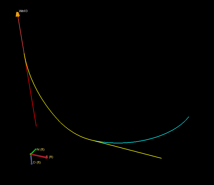
click to enlarge
OBJECT WELL Well3
UNITS m m ft deg deg
COLOR 255 153 0 255
COORDINATES 1000 250 0
WELLBORE WellBore3
COLORWB 255 0 0 255
STATIONS 0
0 0 0
1600 0 0
SIDETRACK Side1 500 WellBore3
COLORWB 255 255 0 255
STATIONS 0
500 0 0
1500 45 90
2000 90 90
3000 90 90
SIDETRACK Side2 2000 Side1
COLORWB 0 255 255 255
STATIONS 0
2000 90 90
3500 90 0
Example 4 (vertical well, using tie-in)
click to enlarge
OBJECT WELL Well4
COORDINATES 500 800 0
TIEIN 200 0 0 100 150 500
WELLBORE WellBore4
500 0 0
1500 0 0
Example 5 (vertical well, minimum / all optional fields left out )
click to enlarge
OBJECT WELL Well5
WELLBORE WellBore5
0 0 0
1500 0 0